
In the daily use of high-power components, due to the limitations of local space and location, ordinary process heat sinks are usually unable to solve the heat dissipation of high heat chips. Therefore, using high-efficiency heat transfer heat pipes is a better choice. Of course, how to make good use of the position of the heat pipe, especially at the bottom of the heat sink, is very important. The following is the experience gained by Kenfa tech engineers in daily use and practice, and it is also the result of software simulation analysis.
When the base plate of the heat pipe is perpendicular to the fins, the heat pipe can transfer heat to each fin more effectively. Because the heat can spread uniformly from the bottom of the heat pipe to the fins in the vertical direction, the temperature distribution on the fins is more uniform as a whole, thus making use of the area of more fins to dissipate heat. If the base plate of the heat pipe is parallel to the fins, the heat may be concentrated in the local fin area contacted by the heat pipe, and the heat dissipation ability of the entire fin array cannot be fully utilized, which will reduce the heat dissipation efficiency. However, this is not absolute. Some complex heat sink designs can also improve the heat dissipation effect to a certain extent when the base plate of the heat pipe is parallel to the fins through special heat pipe bending processes.
We take a 100 W laser pump source module as an example to compare the heat distribution of the fins perpendicular and parallel to the heat sink of the heat pipe within a determined size range. Set heat source based on customer size and structure location. Based on the consideration of a heating surface.Laser base is copper material with 1mm thickness. The contact surface between laser modules and heat sink is made of 0.1mm thermal conductive silicone grease, with a thermal conductivity coefficient of 3.0W/(m·K).

Ambient temperature 60 ℃.Thermal radiation is not considered.Turbulent flow regime.Operating pressure 101325N/m2 on Natural convection.

The number of meshes is 286933.Set uniform mesh params.Mesh assemblies separately.Allow multi-level meshing.Allow minimum gap changes,Divide the grid using a discontinuous grid mode, with a heat pipes grid level of 3 and other characteristic grid levels of 2.
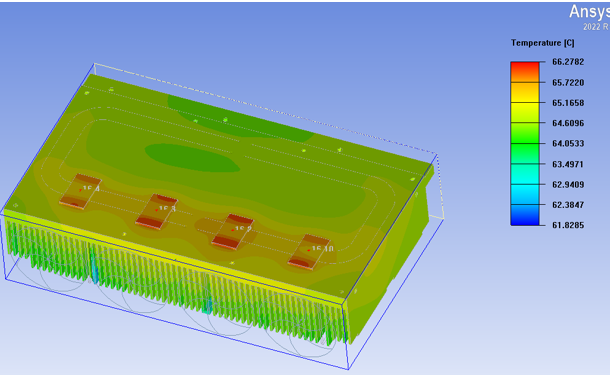
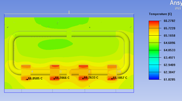
The temperature distribution in the above figure shows that when the heat pipe is perpendicular to the fin of the skived fin heat sink, the temperature distribution is relatively uniform and the heat diffusion is also relatively uniform, with a maximum temperature of 66.7 degrees.
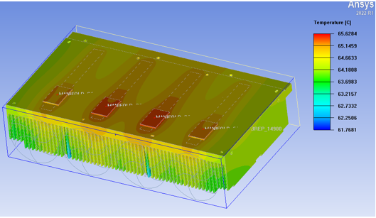
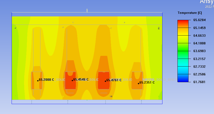
The temperature distribution in the above figure shows that when the heat pipe is parallel to the fins of the radiator, the temperature distribution is relatively uniform and the heat diffusion is also relatively uniform, with a maximum temperature of 65.6 degrees Celsius
So, based on the vector diagrams of the two thermal analyses above, the difference between the two can be seen. From the design of the heat pipe perpendicular to the heat sink fins, the temperature is uniform, and only two heat pipes are used, which can take away a large amount of heat. At the same time, the four laser pump source modules have the same temperature, so there will be no temperature difference. Another important reason is that if one of the fans fails, this can ensure that the heat is also evenly distributed;
Similarly, in the design where the heat pipe is parallel to the fin of the heat sink, the temperature distribution is uneven, and four heat pipes are used to take away a large amount of local heat. At the same time, the four laser pump source modules have inconsistent temperatures, resulting in temperature differences. If one of the fans fails, the local temperature will be higher than the others. Therefore, this design perpendicular to the fin of the radiator will result in uneven temperature distribution, providing another way for engineers to consider when choosing the number of fans.
So, when designing heat pipe heat sinks, we can consider costs such as the number of heat pipes and fans to design a suitable thermal design scheme. Our Kenfa engineers can provide customers with the best thermal design scheme and optimized design scheme.


