We will use professional thermal analysis software to design the optimal scheme for customers, then confirm the feasibility of the theory with engineers, and then start to make samples for testing
Heat Pipe Heat Sink For 622W TEC Cooling Solution
Our customer requires a customized heat sink, and the size space of the heat sink has been defined to handle around 600W of TEC heat. The customer is using four TEC cooling devices for spectral analysis instruments in the medical industry, and the stability of temperature determines the precision of the data. Therefore, it is necessary to control the temperature of the TEC hot surface to below 75 degrees so that the TEC cold surface can operate normally and achieve a temperature difference of around 45 degrees.So the skived fin heat sink with heat pipes is the best choose.
Designed Requirements
TEC thermal power is 155.7x4pcs =622.8W;
Forced convection fan 6025 50CFM each ,2pcs;
Heat sink size: 180x80x42mm;
Heat sink surface is ased below: 75 degrees;
Soldering process ;
Our Thermal Solution
Skived fin heat sink with heat pipes 10pcs (D6.35).Because this is a high-power heat dissipation solution, it is necessary to reduce the thermal resistance between the heat sink base plate and fin. We have removed the soldering process and changed it to the Skived fin heat sink process;
Meanwhile, the area used for TEC is relatively small, with an area of 20X160mm. Therefore, we adopt a heat pipe solution by pressing the heat pipe into the bottom plate of the skived fin heat sink. This can evenly distribute the heat at the bottom of the entire heat sink, which is beneficial for heat dissipation after fin conduction.Greatly improved heat transfer efficiency.
Thermal Design
3D Drawing in Pro/E
The design of the 3D model requires the parameter settings in the software to have a fin thickness of 0.5mm and a spacing of 1.5mm for the heat sink. This is because the fan pressure of 6025 is relatively high, so the fins of the heat sink are relatively dense, usually around 2.0-2.5. Of course, this depends on the length of the fins and the selection of the fan.
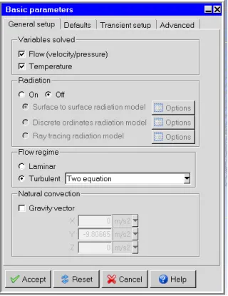
Basic Parameter Setting
● Ambient temperature 25 ℃
● Thermal radiation is not considered
● Turbulent flow regime
● Operating pressure 101325N/m2
● on Natural convection
● The number of meshes is 1043370
● Set uniform mesh params
● Mesh assemblies separately
● Allow multi-level meshing
● Allow minimum gap changes
● Run the solution and get the function curves
● The running step is 1000, and the actual function converges to 900 steps
● The convergence factor flow value is 1xe-5(0.00001)
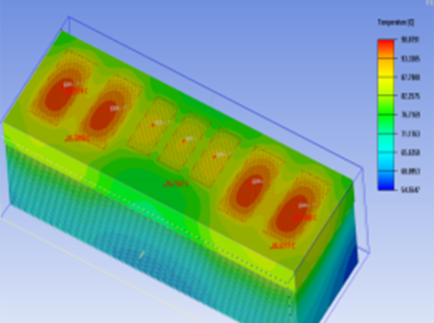
● The maximum surface temperature of TEC is 81.75℃; Average value 75.4℃
● TEC base is made of Ceramic material. The maximum heat sink surface Heat pipes can effectively achieve uniform temperature
● Flow rate of the fan during operation
● The maximum speed is 14.47m/s (Point distribution options uniform set 900)
Thermal Design Results
We try to design this heat sink using sodering technology once. The fin is stamped and nickel plated on the surface, and the heat pipe is directly in contact with the TEC. We found that this method is not as effective as the fin removal process for the heat sink. This is because the height of the heat sink is only about 40, so the heat transfer is not affected by the height. In the end, we came to a conclusion that the height of the heat sink is around 40-45mm, Not affected by high conductivity, we ultimately decided to use the skived fin process to produce this product for our customers.