
FAQs For Liquid Cold Plates
Our sales engineers and customer engineers have doubts and fundamental questions about some concepts and designs of liquid cold plates. Through the content of this article, you can refer to many technical parameters in the design process of liqid cold plates.
Frequently Asked Questions
You can click on the section of your interests:
- 1. What is a liquid cooling plate?
- 2. What parameters are required to design a liquid cooled plate?
- 3. What are the processing techniques for liquid cooled plates?
- 4. What are the advantages of liquid cooled plates compared to traditional air-cooled heat sinks?
- 5. The Application of Liquid Cooled Plates in Data Centers.
- 6. What is the key role of liquid cooled plate in battery and motor heat dissipation?
- 7. How to design the flow channel structure of a liquid cooling plate based on different heating source powers and shapes?
- 8. How to design flow channels to ensure uniform heat dissipation for irregular heating chips?
- 9. What are the advantages and disadvantages of different metal materials of liquid cold plate?
- 10. How to configure the flow rate and pressure of the liquid cooling plate and circulating water pump to achieve the best heat dissipation effect?
- 11. What is the pressure resistance standard for general industrial and automotive grade liquid cold palte ?
- 12. What is the reasonable flow range of coolant inside the liquid cooling plate based on different heat dissipation power? For example, the flow rate of a 1000W heat source and a liquid cold plate. How many liters per minute do we need to reach?
- 13. How to minimize the weight and size of liquid cooled plates to ensure optimal heat dissipation performance?
- 14. The influence of microchannel design on the performance of liquid cooled plates
1. What is a liquid cooling plate?
The liquid cooling plate is an efficient heat exchange device. Structurally, it is mainly made of metal materials, commonly copper or aluminum. Because copper has a high thermal conductivity and aluminum is relatively low – cost and lightweight, these metals can conduct heat quickly.The core part is the channels designed inside. The cooling liquid (usually water or water – based coolant with special additives, and there are also other specially formulated liquids) circulates in these channels. When the liquid – cooling plate is in close contact with the heating components, the heat is transferred from the heating components to the liquid – cooling plate. The cooling liquid flows through the channels, absorbs the heat of the liquid – cooling plate, and takes the heat away, thus realizing the cooling of the heating components.In terms of application scenarios, the liquid – cooling plate is widely used in the electronic field. For example, in high – performance servers, key components such as CPUs and GPUs generate a large amount of heat, and the liquid – cooling plate can effectively reduce the temperature of these components to ensure their stable operation. In the field of electric vehicles, the battery and the motor will generate heat during operation, and the liquid – cooling plate can dissipate heat for these components to ensure the performance and safety of the battery and extend the service life of the battery.
2. What parameters are required to design a liquid cooled plate?
Thermal load: It is necessary to clarify the heat that the liquid – cooling plate needs to take away. This depends on the power of the heating elements in contact with it and is the basis of the design. The unit is usually watts (W).
Thermal resistance: It reflects the ability of the liquid – cooling plate to resist heat transfer. The smaller the thermal resistance, the better the heat dissipation effect. The unit is kelvin per watt (K/W).
Ambient temperature: The temperature condition of the working environment of the liquid – cooling plate. For example, in some industrial environments, the temperature may be relatively high, while in ordinary electronic equipment, the ambient temperature is relatively low. The unit is degrees Celsius (℃) or kelvin (K).
Target operating temperature: That is, the temperature range that the liquid – cooling plate needs to maintain for the heating element. Different elements (such as high – performance chips or batteries) have different optimal operating temperature ranges. Flow rate: The flow rate of the coolant in the flow channels of the liquid – cooling plate. It directly affects the heat transfer efficiency. Generally, it is expressed in liters per minute (L/min) or cubic meters per second (m³/s).
Specific heat capacity: Different coolants (such as water, ethylene glycol solution, etc.) have different specific heat capacities. The larger the specific heat capacity, the more heat is absorbed or released under the same mass and temperature change. The unit is joules per kilogram kelvin (J/(kg·K)).
Viscosity: It affects the flow resistance of the coolant in the flow channels. The larger the viscosity, the greater the flow resistance and the easier it is to generate pressure loss when flowing in the pipes. The unit is pascal – seconds (Pa·s).
Thermal conductivity: The higher the thermal conductivity of the material (such as copper, aluminum, etc.) of the liquid cooling plate, the faster the heat is transferred from the heating element to the coolant. The unit is watts per meter kelvin (W/(m·K)).
Mechanical strength: Ensure that the liquid cooling plate will not be deformed or damaged during processing, installation and use, including tensile strength, compressive strength and other indicators.
Length, width and depth of the flow channel: These parameters determine the cross – sectional area and total volume of the flow channel, which in turn affect the flow rate and the residence time of the coolant in the flow channel. The units are meters (m) or millimeters (mm).
Welding technology: For example, using different welding methods such as FSW ,Brazing, laser welding and argon arc welding has different effects on the sealing and welding strength of the liquid cooling plate. The welding quality is directly related to the reliability and service life of the liquid cooling plate.
Flow channel layout: It can be in various forms such as straight channels, serpentine channels, parallel channels, etc. Different layouts have different effects on the flow distribution and pressure loss, and need to be designed according to specific heat dissipation requirements and fluid characteristics.
3. What are the processing techniques for liquid cooled plates?
The main production processes of the liquid – cooling plate are as follows: Friction stir welding, which uses the friction between the stirring head and the workpiece to generate heat to soften the material and form a weld seam. This welding method has high quality and does not require welding wire; brazing, which uses a low – melting – point brazing material that is heated and melted to fill the weld seam, achieving good connection effect; vacuum diffusion welding, in which the welded parts are in close contact in a vacuum environment and atoms diffuse to achieve connection, resulting in a high – strength weld seam; argon arc welding, which conducts welding with the protection of argon gas for the arc, and the weld seam is beautiful and has stable quality; stamping process, which stamps the metal plate into a specific shape, and is suitable for the preliminary forming of the liquid – cooling plate with a complex structure. These processes ensure the quality and performance of the liquid cooling plate.
4. What are the advantages of liquid cooled plates compared to traditional air-cooled radiators?
Liquid cooling plates have a high heat dissipation efficiency and can make the temperature of heating components more uniform. They can meet the heat dissipation requirements of high – power – density equipment and are less affected by the ambient temperature. On the other hand, air – cooling heat dissipation has a simple structure, low cost, and does not require additional cooling liquid. Its installation and maintenance are relatively convenient. In scenarios with limited space, liquid – cooling plates can arrange heat dissipation components more compactly. However, in some low – power equipment where the heat dissipation requirements are not extremely high, air – cooling still plays an important role due to its economy and easy operation.
5. The Application of Liquid Cooled Plates in Data Centers
In data centers, the liquid cooling plate plays a crucial role. Since servers and other equipment in data centers generate a large amount of heat during operation, the liquid – cooling plate can dissipate heat efficiently. It closely adheres to the heating elements, and the coolant circulates in the internal channels to quickly take away the heat. Compared with traditional air – cooling, the liquid – cooling plate has higher heat dissipation efficiency and is quieter. This helps to reduce the temperature in the data center, ensure the stable operation of the equipment, reduce failures and performance degradation caused by overheating, and extend the service life of the equipment, providing a powerful heat dissipation guarantee for the efficient and reliable operation of the data center.
6. What is the key role of liquid cooled plate in battery and motor heat dissipation?
In terms of battery heat dissipation, the liquid cooling plate plays a crucial role. During the charging and discharging process of the battery, heat is generated. If the heat accumulates, it will affect the performance and safety of the battery. The liquid – cooling plate is closely attached to the battery. Through the circulating flow of the coolant, it efficiently takes away the heat and keeps the battery temperature within a suitable range, thereby extending the battery life, improving the charging and discharging efficiency of the battery, and reducing the risk of thermal runaway.For motor heat dissipation, when the motor is running, heat is generated due to the current passing through components such as windings and iron cores. The liquid – cooling plate can quickly transfer the heat to the coolant. Since the liquid has a large specific heat capacity, it can absorb a large amount of heat while the temperature increase is relatively small. This ensures the stability of the motor’s working temperature, reduces the damage to the insulation of the motor windings caused by high temperature, reduces the loss of the motor, improves the power output and operating efficiency of the motor, and ensures that the motor can operate reliably under different working conditions.
7. How to design the flow channel structure of a liquid cooling plate based on different heating source powers and shapes?
Increase the flow rate: Since a high – power heat source generates a large amount of heat, a larger coolant flow rate is required to take away the heat in a timely manner. The width and depth of the flow channels can be increased or the number of flow channels can be increased, for example, by using multiple parallel flow channels to increase the overall flow rate of the coolant.
Optimize the flow channel layout: Design a more complex flow channel layout, such as a serpentine or spiral flow channel, to increase the contact area and contact time between the coolant and the heat source, thereby improving the heat dissipation efficiency.
Appropriately reduce the flow rate: For a low – power heat source, an excessive coolant flow rate is not required. The size of the flow channels can be appropriately reduced to reduce the flow rate of the coolant and avoid unnecessary energy loss.Simple flow channel structure. A simple direct – current channel can be used. This structure is simple and has low processing costs, and at the same time can meet the heat dissipation requirements of low – power heat sources.
Matching shape design: When the heat source is in a regular shape, the flow channels can be designed into a geometric shape similar to the shape of the heat source. For example, for a square heat source, a square flow channel grid can be designed; for a circular heat source, an annular flow channel can be designed. This allows the coolant to be evenly distributed within the flow channels and ensures a uniform heat dissipation effect on all parts of the heat source.Symmetrical layout.When designing the flow channels, a symmetrical layout is used to allow the coolant to flow evenly towards the heat source from all directions, further improving the uniformity of heat dissipation.
Partition design: Divide an irregular – shaped heat source into several relatively regular areas, and then design the corresponding flow channel structure for each area. For example, for a polygonal heat source, it can be divided into multiple triangular or quadrilateral areas, and then the flow channels can be designed respectively.
Flexibly adjust the flow channels: According to the specific shape of the heat source, flexibly adjust the width, depth, and direction of the flow channels so that the flow channels can fit the contour of the heat source as closely as possible to ensure that the heat can be effectively transferred to the coolant.
8. How to design flow channels to ensure uniform heat dissipation for irregular heating chips?
According to the heating characteristics of the chip, divide the surface of the irregular chip into multiple different regions. These regions can be divided according to factors such as the density of heat distribution and the parts where heat is concentrated. For example, for a chip with multiple cores and uneven heating, divide the area where each core is located into a separate region.Evaluate the heat dissipation requirements of each region to determine the coolant flow rate and heat dissipation efficiency required for each region. For example, th e. flow channel design corresponding to the region with a large amount of heat generation should be more conducive to the rapid flow and heat exchange of the coolant.
9. What are the advantages and disadvantages of different metal materials of liquid cold plate?
Common materials for liquid cooling plates include copper, aluminum, and stainless steel.The copper liquid cooling plates has the advantage that its thermal conductivity is extremely outstanding. With a high thermal conductivity coefficient, it can transfer heat out quickly and is suitable for high – power heat dissipation scenarios. It also has good processing performance and can be made into complex structures. However, copper has a high cost and a large density, resulting in a heavy weight.
The aluminum liquid cooling plate has a low cost, and the price is affordable, which is beneficial for reducing the overall cost. It is lightweight and suitable for equipment that is sensitive to weight. At the same time, it has good thermal conductivity and can meet most of the conventional heat dissipation requirements. Nevertheless, aluminum has weak antioxidant properties and is prone to form an oxide film that affects thermal conductivity, and its mechanical strength is not as good as other materials.The stainless – steel liquid cooling plate has strong corrosion resistance and can be used in harsh environments such as wet, acidic, and alkaline environments. It has high mechanical strength and can withstand large external forces. But the disadvantage is that its thermal conductivity is relatively poor, and the heat transfer efficiency is low, so it is not very suitable for occasions with extremely high requirements for heat dissipation efficiency.
10. How to configure the flow rate and pressure of the liquid cooling plate and circulating water pump to achieve the best heat dissipation effect?
Firstly, it is necessary to evaluate the heating power of the heat source (such as chips, batteries, etc.). Generally speaking, the greater the heating power, the greater the required coolant flow rate. For example, for a high – power server CPU, a relatively high flow rate (such as several tens of liters per minute or even higher) may be required to take away the heat in a timely manner to ensure that the temperature does not exceed the safe working range.
Adjust the flow rate according to the heat exchange efficiency of the liquid – cooling plate. If the liquid – cooling plate is designed with a large heat exchange area and an efficient flow channel structure, a relatively low flow rate may be sufficient to meet the heat dissipation requirements; otherwise, the flow rate may need to be increased. Generally, the heat exchange efficiency of the liquid – cooling plate is related to factors such as the design of the flow channel and the thermal conductivity of the material.
The flow rate is not the larger the better. An excessive flow rate may lead to excessive system pressure, increased energy consumption, and unnecessary impact on the liquid – cooling plate and pipes. A too – small flow rate cannot take away the heat in time, resulting in poor heat dissipation effect. It is necessary to make fine – tune adjustments in practice according to the specific heat dissipation effect and system operation conditions to find a flow value that can meet the heat dissipation requirements without causing waste of resources.
The structure, length, bending degree of the internal flow channels of the liquid – cooling plate, and the thickness of the pipes will all affect the resistance of the system. For example, a complex flow channel design (such as a serpentine flow channel) and a long pipe will increase the resistance of the system. At this time, the circulating water pump needs to provide a higher pressure to ensure the normal flow of the coolant. Generally speaking, according to the total resistance of the system, a water pump with a suitable pressure range can be selected. The common pressure range of water pumps varies from several pascals to several tens of pascals.
Ensure that the pressure can overcome the local resistance in the system. Parts such as pipe joints and valves in the system may cause local pressure drops. When designing the system, these factors that affect the pressure should be considered, and the pressure of the water pump should be reasonably selected to ensure the stable flow of the coolant in the entire liquid – cooling cycle system.
The pressure fluctuation of the circulating water pump will affect the stability of the liquid – cooling system. Therefore, it is very important to select a water pump with a stable pressure output. Some high – quality circulating water pumps adopt advanced control technologies (such as frequency conversion control) to maintain the stability of the pressure, thus ensuring that the liquid – cooling system can provide reliable heat dissipation effects under different working conditions.
11. What is the pressure resistance standard for general industrial and automotive grade liquid cold plate?
Industrial – grade liquid – cooling plates:The pressure resistance capacity of industrial – grade liquid – cooling plates is usually around 1 – 3MPa. This is because in the general industrial environment, the liquid – cooling system mainly needs to deal with the regular equipment operating pressure, a certain degree of pressure fluctuations in the pipeline, and the pressure changes generated during the coolant circulation process. For example, in the cooling systems of some industrial automation equipment and communication base station equipment, a pressure resistance capacity of 1 – 3MPa can meet the requirements of most usage scenarios.
Automotive – grade liquid – cooling plates, due to the complex operating environment of the vehicle, including vehicle vibration, a large temperature change range, and extremely high requirements for safety, their pressure resistance standards are usually higher. The pressure resistance capacity of automotive – grade liquid – cooling plates is generally around 3 – 5MPa. In the cooling of the vehicle’s power system (such as the battery pack and drive motor of an electric vehicle), a higher pressure resistance capacity can ensure the stable operation of the liquid – cooling system under various vehicle working conditions (such as sudden acceleration and sudden braking), and prevent safety problems such as the rupture of the liquid – cooling plate and coolant leakage caused by sudden pressure changes. At the same time, the relevant standards and regulations in the automotive industry also have strict requirements for the safety and reliability of the liquid – cooling system, which also promotes the automotive – grade liquid – cooling plates to have higher pressure resistance performance.
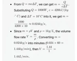
12. What is the reasonable flow range of coolant inside the liquid cooling plate based on different heat dissipation power? For example, the flow rate of a 1000W heat source and a liquid cold plate. How many liters per minute do we need to reach?
According to the principle of thermal equilibrium, the heat taken away by the coolant is equal to the heat generated by the heat source. The heat formula is Q , where Q is the heat (in joules), m is the mass flow rate (in kilograms per second), c is the specific heat capacity of the coolant (the specific heat capacity of water is about 4200j/kg.˚C ), and Δtm is the temperature difference between the inlet and outlet of the coolant. The relationship between the mass flow rate and the volume flow rate V (in liters per minute) is ρ=m/V , where ρ is the density of the coolant (the density of water is about 1000kg/m3=1kg/L) For a 1 – kilowatt (1000W) heat source, assume that the temperature difference Δtm between the inlet and outlet of the coolant is (the general value range is5-15˚C ).
13. How to minimize the weight and size of liquid cooled plates to ensure optimal heat dissipation performance?
To minimize the weight and size of the liquid cooling plate while ensuring the heat dissipation effect, efforts can be made from multiple aspects. In terms of design, micro – channels can be adopted and the size of the channels can be made smaller to increase the contact area between the coolant and the channel walls and improve the heat dissipation efficiency; or a fractal flow channel can be designed to achieve a complex and efficient coolant path in a small space. In terms of layout, according to the shape of the heat source, a closely fitting design can be carried out to reduce space waste. It can also be integrated with components such as radiators. In terms of material selection, new composite materials with high thermal conductivity and low density, such as carbon – based composite materials or metal foam materials, can be used to reduce the weight while ensuring the thermal conductivity. In the processing technology, laser processing and 3D printing technology can be used to create fine channel structures, accurately control the size, and reduce the use of materials. By integrating these aspects, the optimal heat dissipation effect of the liquid cooling plate can be achieved while minimizing the weight and size.
14. The influence of microchannel design on the performance of liquid cooled plates
In terms of heat dissipation efficiency, the micro – channel can greatly increase the heat exchange area. Due to its small channel size, more channels can be arranged within the same volume, increasing the contact area between the coolant and the wall surface and enabling rapid heat transfer. Moreover, the micro – channel makes the coolant flow close to laminar flow, with a thin liquid layer and a significant wall effect, strengthening the heat transfer process.In terms of pressure and flow characteristics, the micro – channel will increase the flow resistance. Because of its small size, the frictional resistance of the coolant increases, requiring a higher pressure to push the coolant to flow. At the same time, the requirement for flow uniformity is higher, and non – uniformity will affect the heat dissipation effect.From the perspective of materials and processing techniques, the micro – channel has high requirements for the thermal conductivity and processing performance of materials. Materials with high thermal conductivity and easy processing need to be selected. And high – precision processing techniques such as laser processing and 3D printing are required for processing. Although these techniques can meet the requirements, they are costly and complex to operate.
Our engineers have summarized many blog papers on liquid cooled plates during the design and production process, which can provide some references for our clients’ engineers to design。
1,Deep Dive into NVIDIA GB200 Liquid Cooling Plate Design.
2, Salt Spray Reliability Test of Liquid Cooling Plates Based on IEC 60068-2-52 Standard.
3, Analysis of Corrosion Issues and Material Selection for Liquid Cooling Plate Channels.
4, Liquid for Cooling System: Everything You Need to Know.
5, Liquid Cold Plates: The Ultimate Guide to Efficient Thermal Management Solutions
6, Top 10 Thermally Conductive Materials You Need to Know in 2025.
7, How to Prevent Leakage in Liquid Cooling Plate Design.
8, Design and Optimization of Flow Channels for Liquid Cooled Plates.
9, How to optimize the microchannel design of liquid cold plate.
10, Selection of coolant for liquid cooling systems.
11, How can I tell the pros and cons of Liquid Cold Plate design?
12, Copper Liquid Cooling Plate VS Aluminum Liquid Cooling Plate.
13, What is an Electric Vehicle liquid cold plate?
14,FSW Weld Whitening and Anodizing Adaptation Technology

