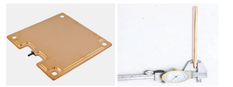
Heat pipe (Heatpipe) and Vapor Chamber (VC) are widely used in high power or high integration electronic products. When used properly, it can be simply understood as a component with a very high thermal conductivity. It is not difficult to understand that heat pipe and VC can effectively eliminate diffusion thermal resistance
Key words
Heat pipe
Vapor Chamber
Article contents
The most common application example of heat pipe is embedded in the radiator, the heat of the chip fully spread on the radiator substrate or fin. When the heat emitted by the chip is transferred to the radiator through the heat-conducting interface material, the heat can be transmitted along the heat pipe with very low thermal resistance due to the high thermal conductivity of the heat pipe. In this case, the heat pipe is connected to the radiator fin, so that the heat can be more effectively dissipated through the radiator into the air. For the heat sink embedded only in the substrate, when the heating area of the chip is relatively small, it is directly transferred to the substrate of the radiator, which will make the temperature distribution of the substrate have a large non-uniformity. After the addition of heat pipes, due to the high thermal conductivity of heat pipes, it can effectively reduce the uneven temperature and improve the heat dissipation efficiency of the radiator.
Heat pipe and VC have high equivalent thermal conductivity because their internal heat transfer mechanism is phase transformation heat. From the range of surface heat transfer coefficient, it can be seen that the phase transformation heat is the most efficient convective heat transfer. In heat pipe or VC, boiling heat transfer is carried out in the evaporation section, and steam condensation is carried out in the condensation section.
The most important performance indexes of heat pipe and VC are the maximum heat transfer Qmax, thermal resistance R and starting temperature T0. Defined respectively as follows: maximum heat transfer rate Qmax: the calorific value of Qmax value equal to the following situation: heat pipe evaporation or VC joint calorific value of Q fever source, the measured temperature difference between evaporation and condensation within the prescribed scope (usually used in engineering 5 ℃ as decision criteria), the unit is W. thermal resistance R: when heat transfer size of Q, the actual measured the temperature difference between the evaporator and condenser Δ T, thermal resistance value is Δ T/Q, the unit is ℃ / W or K/W.
Starting temperature T0: The heat pipe is a process of evaporation and condensation. But the evaporation and condensation of fluid must occur under certain temperature and pressure conditions. Starting temperature T0 refers to the minimum temperature required for the formation of phase transformation heat cycle in the heat pipe or VC cavity.
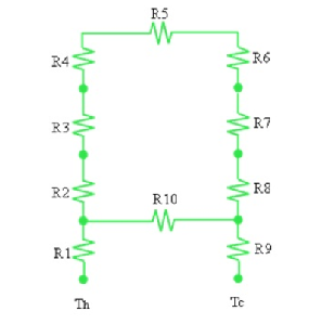
There are many factors affecting the performance of heat pipe and VC, and the mechanism analysis needs to clarify the heat transfer process in the cavity. When the evaporation section of the heat pipe is heated, the liquid in the suction core inside the evaporation section evaporates, and the pressure here increases, and the vapor transfers to the condensing section under the action of pressure difference. When the gas is transferred to the condensate section, it is condensed into a liquid. The condensed liquid is transferred to the evaporation section through capillary force in the suction core, forming a cycle. As follows:
R1: (convective) heat transfer resistance between the heat source and the outer wall of the evaporation section
R2: radial heat conduction resistance of the wall of the evaporation section.
R3: (radial) thermal conductivity resistance of the suction core of the evaporation section
R4: thermal resistance of evaporation heat exchange on the inner surface of the evaporation section
R5: thermal resistance of the axial flow of steam
R6: thermal resistance of the condensation heat exchange on the inner surface of the condensation section
R7: thermal conductivity resistance of the suction core of the condensation section
R8: thermal conductivity resistance of the tube wall of the condensation section
R9: (Convection) heat transfer resistance of the outer wall surface of cold source and condensation section R10: axial thermal resistance of tube wall and suction core


