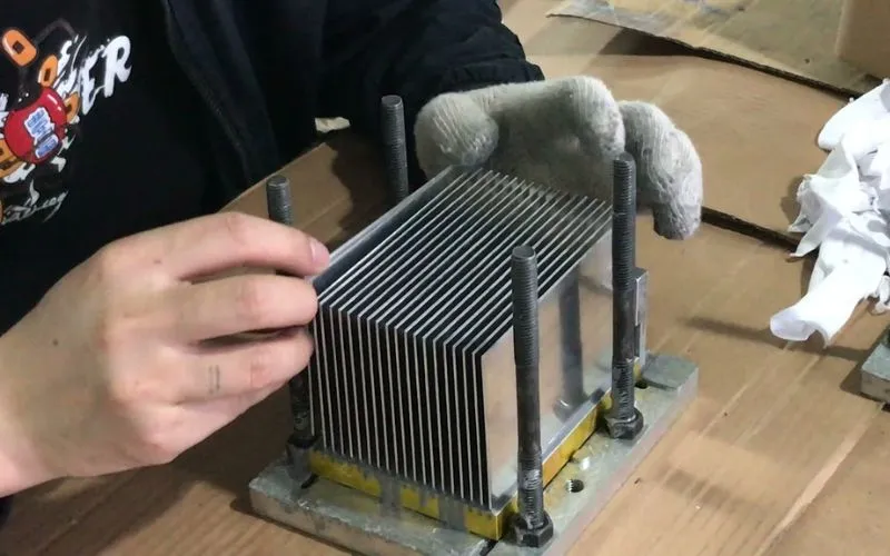
There are various specifications and production processes for liquid cooling plates, but the most important microchannel is the key to determining heat dissipation performance. Therefore, studying and comparing different types of microchannels is a key step in determining the process of liquid cooling plates. However, there are other factors that affect our practical application, such as usage environment, price, etc. Therefore, we must comprehensively consider which type of liquid cooling plate is suitable for our project.But based on theoretical research, we can draw a conclusion. The basis of our research is:
IGBT Module: Total power is 2898 W.
Total power is divided into three parts
60.9% power to IGBT Sources
29.1% power to DIODE sources
10 % power to copper substrate layer between die and Al2O3 substrate to include the connection losses
There are total 18 IGBT sources and 18 DIODE sources.
IGBT source size is 12.56x 12.56×0.14 mm
DIODE source size is 9x9x0.14 mm
Cu Heat spreader is of 162x122x3 mm size
lThe specification of the materials are as per given in Data sheet

For All liquid cold plates:
Overall Length= 250 mm, Overall Width= 150 mm
Total Flow rate= 5.7 lpm
Ambient temperature is 35 oC
Thermal Interface material: K=4.5 W/mK
Runs were done using pure water
• Gun drilled base plate with plugs in the service holes
• Complicate machining, un-flexible design, medium performances
• Milled base plate with cover sealed with O-rings + screws
• Time consuming and unreliable sealing, flexible design, medium performances
• Extruded channels with machined head-blocks
• Reliability issues, low performances, un-flexible design
• Direct cooling under the modules
• limited cooling surface, complicate module substitution, unreliable sealing
• Alternate layers of perforated plates
• high pressure drop, efficient only with limited water flow
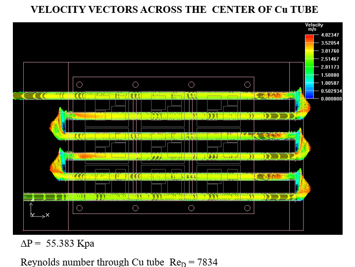
Design1-HiContact copper tubing embedded in an aluminium plate
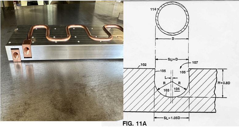
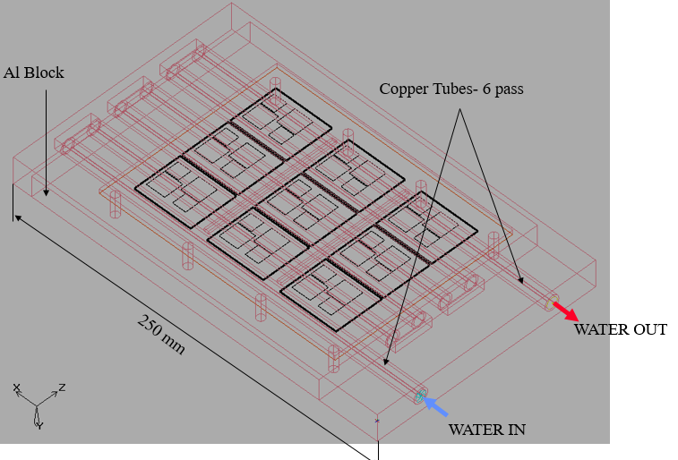
Note: Cu Tube O.D.= 9.525 mm, Wall Thickness = 1.27 mm Cu Tube Pitch = 18.034 mm
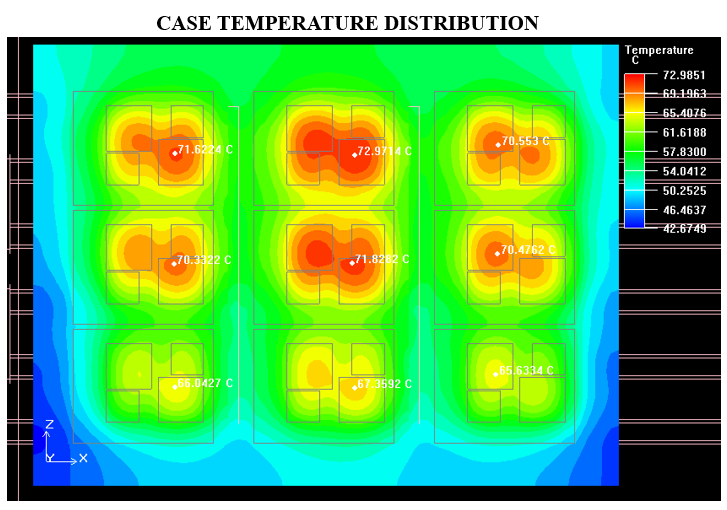
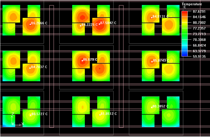
Temperature distribution on IGBT and Diode sources
Design2-Milled Flat Channels with Brazed Cover
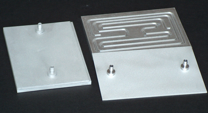
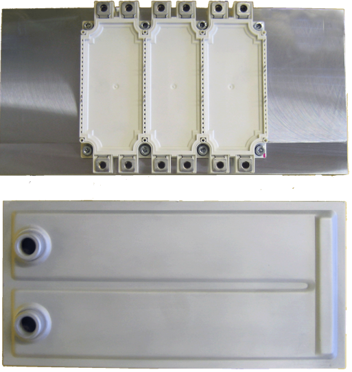
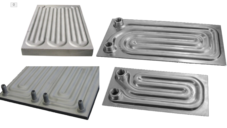
Example of Milled LCP for Electromedical application
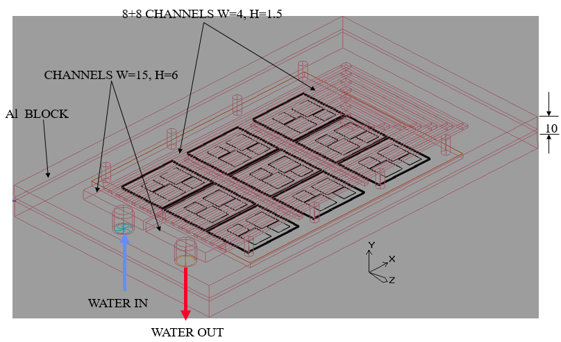
LIQUID CHANNELS W=15, H=6,8+8 LIQUID CHANNELS W=4, H=1.5
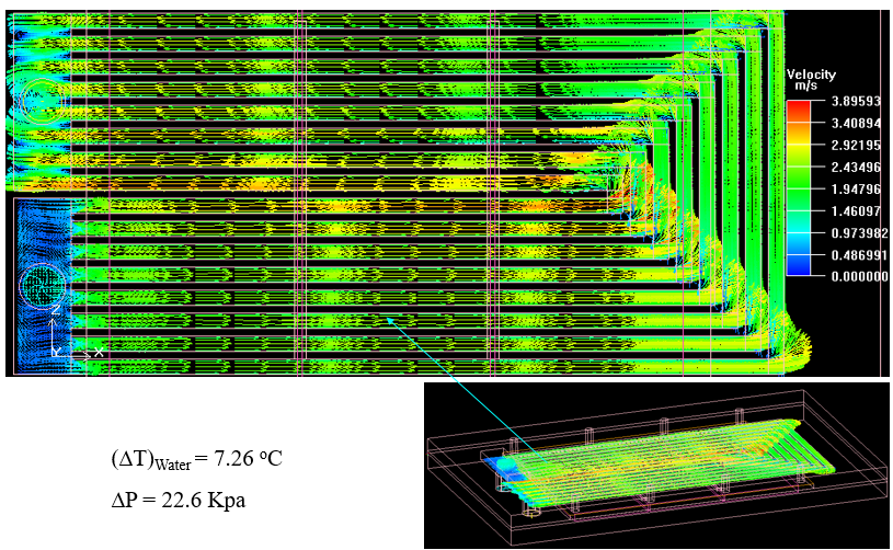
VELOCITY VECTORS ACROSS THE MIDDLE OF LIQUID CHANNELS
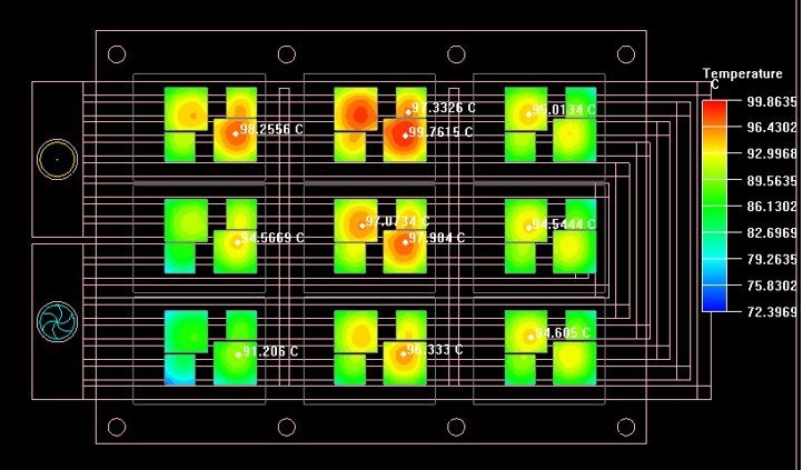
Temperature distribution on IGBT and Diode sources
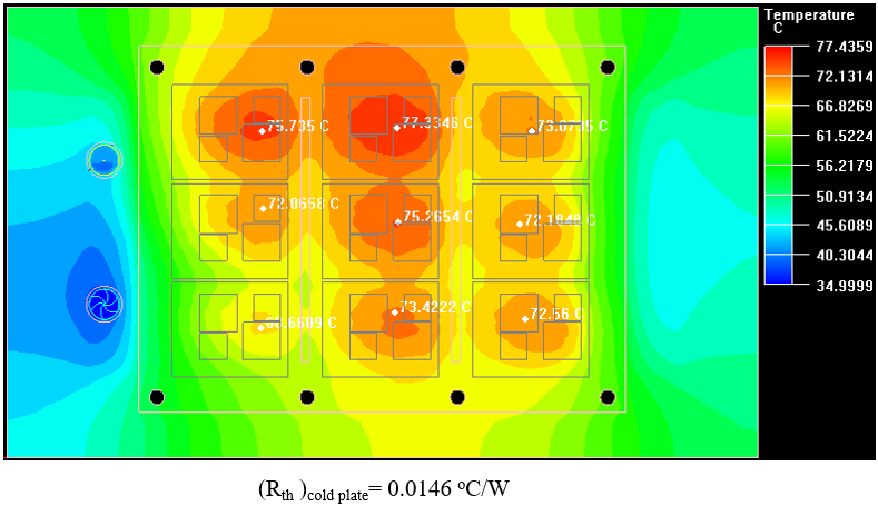
Cold Plate Base Temperature distribution,
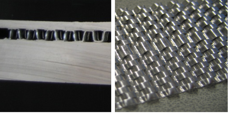
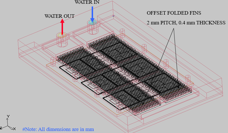
Design3-Thick Offset Fins Blister & Thin Base
VERSION –E2- ICEPAK MODEL
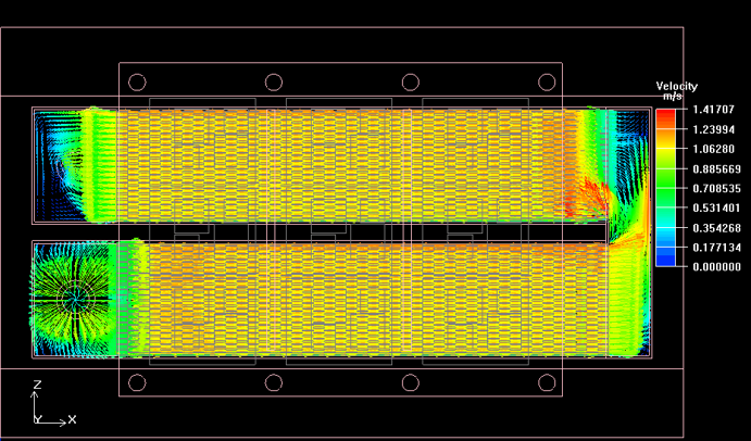
VELOCITY VECTORS THROUGH CENTER OF OFFSET FOLDED FIN,∆P = 26.464 Kpa,Re = 821
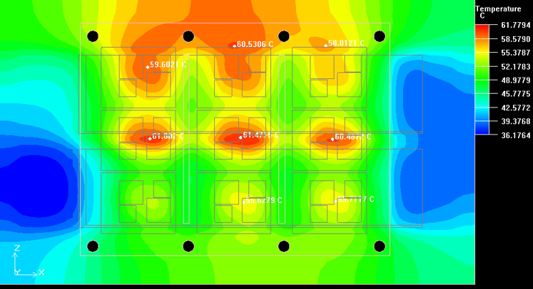
Cold Plate Base Temperature distribution ,(Rth )cold plate= 0.0092 oC/W
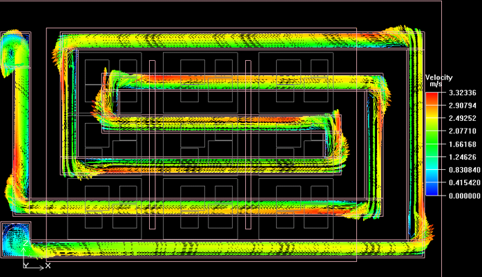
Design4-Snake Blister liquid cold plate
VELOCITY VECTORS THROUGH CENTER OF SNAKE BLISTER.∆P = 46.603 Kpa,Reynolds number through the center of channel Re = 6175
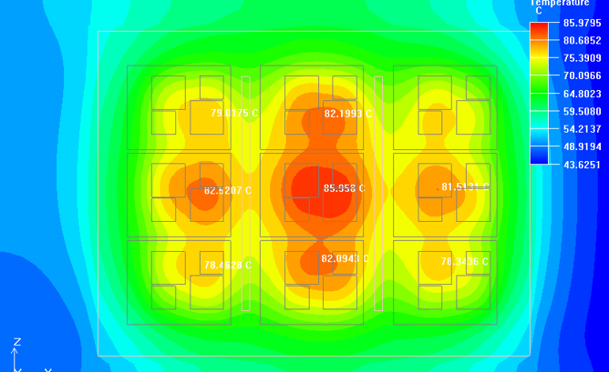
Cold Plate Base Temperature distribution
Design5-Meso Channels liquid cold plates
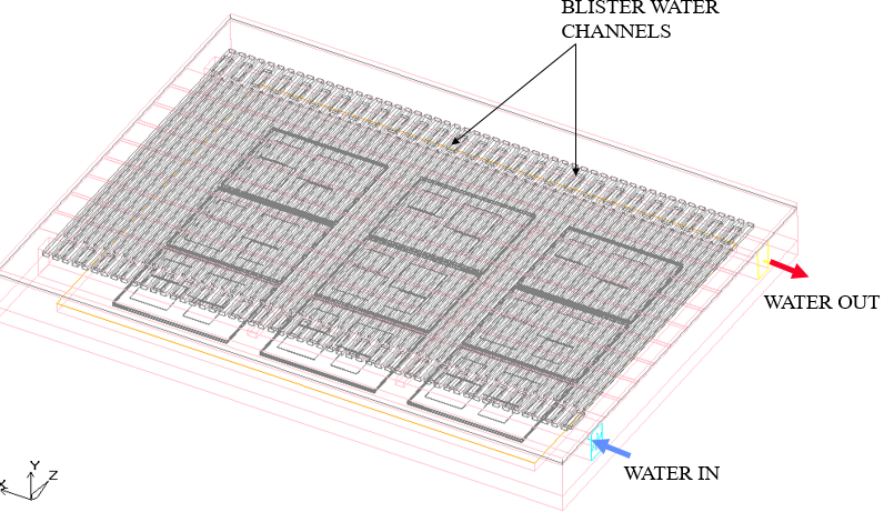
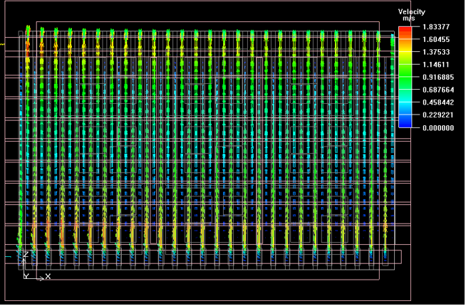
VELOCITY VECTORS ACROSS THE MIDDLE OF BLISTER CHANNEL. ∆P = 6.622 Kpa
Reynolds number through center of Blister channel ReD = 781
Cold Plate Base Temperature distribution
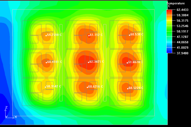
Comparison Summary for Liquid Cold plates
We found through modeling and thermal analysis based on 5 models that the flow velocity and temperature distribution in each channel are different. Therefore, the optimal heat dissipation scheme corresponds to the theoretical data. Based on these data, we compared and analyzed them to ultimately find a cost-effective solution, which means that not all high-performance liquid cooling plates are suitable


