The increasing power of electronic chips has made air-cooling methods of electronics increasingly difficult. Therefore, more and more devices need to use forced convection air cooling heat sinks to control chip temperature. Parallel plate heat sinks is a widely used type of heat sinks
Key words
Thermal resistance
Article contents
In order to select a suitable heat sinks, thermal design first determines the maximum design thermal resistance of the heat sinks. To obtain this value, we must know the maximum shell temperature of the chip, Tcase, thermal power consumption of the chip, Pmod, and the thermal resistance of the chip to the heat sinks, Rint. The maximum temperature Tbase of the heat sinks underside can be given by the following formula:

The maximum thermal resistance of the radiator, Rmax, is given by the following formula:

Tair-in is the cooling air temperature at the inlet. At this point, many thermal engineers began to look in radiator catalogs (or, more often these days, on the Internet) for radiators of the right size, Rhs, and below the specified maximum thermal resistance, Rmax. In many cases, estimating the thermal resistance Rhs of various parallel plate toothed radiators from structural dimensions helps to determine whether a design is feasible. The rest of this article mainly provides basic formulas for such calculations. The thermal resistance is calculated by the following formula:

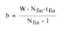
Where h is the heat transfer coefficient of convection. Abase is the bare surface area at the bottom between the heat sinks. Nfin is the number of heat sink teeth. fin is the function of heat sink. Afin is the area of the two sides of each fin. To further calculate, it is necessary to determine the maximum volume of the radiator, which can be determined by its width W, height H, and length L along the direction of the flow. It is also necessary to define the thickness of the fin, tfin. Through these parameters, the channel width between the heat sink can be obtained by the following formula:

The formula for calculating the total area exposed at the bottom is as follows:

The convection heat transfer area of each heat sink is:

In this case, the flow rate (average velocity) V, or flow rate G should be defined. If flow rate is used, the corresponding air velocity between plates is:

To determine the coefficient of convective heat transfer acting on a radiator refer to the relevant Teertstra et al formula. The relevant parameters are Nusselt number, Nu, Reynolds number, Re, and Prandtl number, Pr. Here’s the equation:

The formula for calculating Prandtl number is as follows:

Where is the dynamic viscosity of air. cp is the specific heat of air at normal pressure. k is the thermal conductivity of air. The Reynolds number used in equation (8) is the Reynolds number of rectangular runner. It is defined as:

One is air density. Formula (8) covers almost the whole range of laminar flow. The Reynolds correction (0.26< Reb < 175) and some experimental data verify the validity of formula (8). Using the Nusselt number obtained from formula (8), the convective heat transfer coefficient can be calculated from the following formula:

Here kfin is the thermal conductivity of the heat sink, and the formula for calculating the efficiency of the heat sink is:

Where tanh is a hyperbolic tangent function, and m is given by the following formula:

These equations can be used to estimate the heat dissipation performance of the radiator, that is, the heat resistance from the bottom of the radiator to the air in the intake. It should be noted that the equation for Nusselt number includes the effect of increasing temperature when the air flows through the radiator. To obtain the total thermal resistance Rtot, the conductive thermal resistance of the radiator substrate is added. Therefore, if the heat flow through the base is equalized, the total thermal resistance Rtot can be obtained by the following formula:

To understand these equations, let’s estimate the thermal resistance of a 50 x 50 mm aluminum radiator. The influence of heat sink height and number of teeth on thermal resistance was studied under the conditions of constant velocity and flow, respectively, as shown in FIG. 2 and FIG. 3. Both show that it is limited to reduce heat sink resistance by increasing tooth height and number.
Of course, to determine the actual operation of a radiator in a device it is necessary to know the air speed or flow through the radiator. Obtaining them requires estimating the pressure drop characteristics of the radiator in order to fit it to the corresponding fan or blower, which is a topic we will discuss in a future article.

FIG. 2 The relationship between heat sink tooth height and tooth number and thermal resistance at a flow velocity of 2.5 m/s (492 fpm)

FIG. 3 The relationship between heat sink tooth height and tooth number and thermal resistance at a gas flow rate of 0.0024 m3 / s (5 CFM).


